
Page 186 - Kỷ yếu hội thảo quốc tế: Ứng dụng công nghệ mới trong công trình xanh - lần thứ 9 (ATiGB 2024)
P. 186
th
HỘI THẢO QUỐC TẾ ATiGB LẦN THỨ CHÍN - The 9 ATiGB 2024 177
The maximum injection duration in each cycle
depended on the engine speed and the ability to draw
all the injected fuel into the cylinder. This was
particularly challenging for fuels with low A/F ratios.
The following section will present the simulation
results of mixture formation during gas fuel injection
and propose suitable solutions for engines using
flexible fuels like biogas and hydrogen.
3. RESULTS AND COMMENTS
3.1. Install parts onto the modified engine
Hall sensor installation: Industrial-grade Hall
sensors, encased in stainless steel and designed for
water resistance and vibration tolerance, were used in
this experiment. Two Hall sensors were employed.
One sensor provided a signal 35 degrees before Top
Dead Center (TDC), while the other sensor generated
a signal at TDC. The second sensor was solely used to
verify the ignition timing relative to TDC. In practical
applications, this sensor is not necessary. Both
sensors were mounted on a fixture and attached to the
location of the removed ignition coil on the engine
(Figure 2a).
Servo motor installation: The servo motor is
responsible for controlling the throttle. It is securely
mounted on a bracket. The servo motor shaft is
connected to a lever that is linked to the engine throttle.
The lever rotates from 0° to 60°, corresponding to fully
closed and fully open throttle positions (Figure 2b). A
dual potentiometer is used to simultaneously control
the servo motor and provide the corresponding throttle
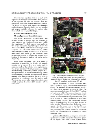
opening value. During operation, the servo motor is Fig. 2. Installing the assemblies on the modified
susceptible to interference from the ignition spark. engine Install the Hall sensor (a), Install the servo
Therefore, the power-noise suppression circuit must motor (b), Install the injector (c), Install the gas fuel
include measures to ensure stable operation of the line (d), Install the ignition assembly (e)
servo motor. Injector installation: A Valtek automotive LPG
injector is used to supply gaseous fuel to the modified
engine. The operating fuel pressure can vary from 0.5
to 2 bar, with a maximum pressure of 3 bar. The
operating voltage is between 10.8 and 14.4 V, and the
coil resistance is 5Ω. The minimum injection time is
3.3ms. The injector is securely mounted on the engine
bracket. Gaseous fuel from the pressurized tank, after
being reduced to 1.5 bar, is supplied to the injector
through an inlet gas pipe. The gaseous fuel from the
injector is delivered to the spray hole through an
outlet gas pipe (Figure 2c). Since the injector cannot
operate when the control pulse is less than 3.3ms, to
ensure stable engine operation at idle, an additional
idle gas supply line must be added after the throttle
(Figure 2d). The idle gas flow is adjusted by a fine-
tuning gas valve.
Ignition coil installation: An integrated automotive
ignition coil is used to replace the old ignition system
of the engine. The entire control system, which
ISBN: 978-604-80-9779-0